For this session you will need the following items:
- Beaglebone Black (BBB)
- Laptop, netbook, or computer
- Micro USB cable for the BBB
- breadboard populated with components (see previous post)
- SSH client like PuTTY installed on the computer
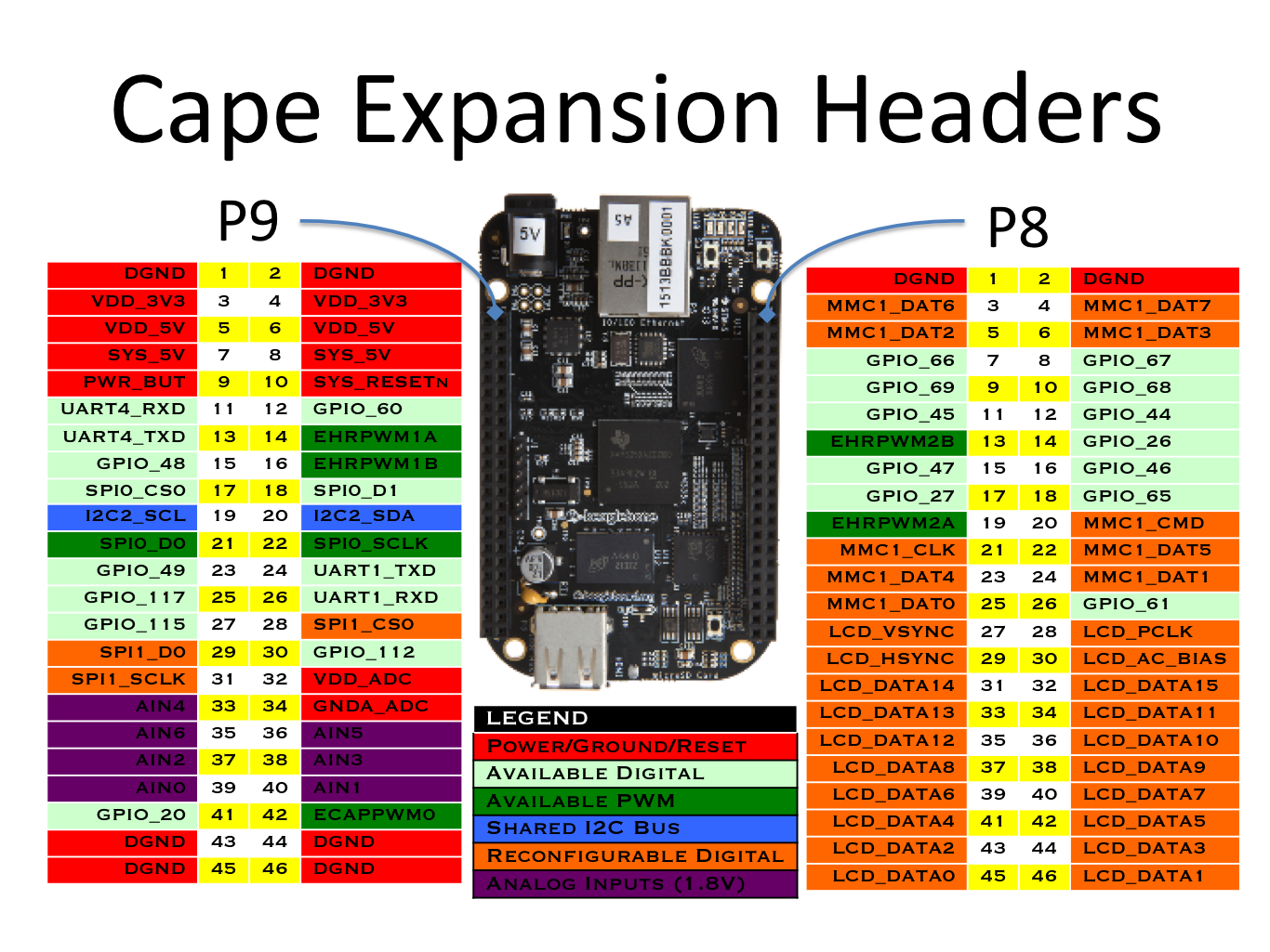 |
| Image from BBB System Reference Manual |
As you can see there are two expansion headers labeled P8 and P9. The pins we're interested in for this experiment are the GPIO_XX pins (light blue), the AINX pins (purple), the VDD_ADC pin (P9-32) and the GNDA_ADC pin (P9-34) (red). For now we'll need to choose two of the GPIO pins to drive the red and green LEDs and one of the ADC pins to read the voltage from our thermistor voltage divider network. We'll also need to use one of the DGND pins to provide gound to our breadboard ground rail so the LEDS have a complete circuit.
Let's choose GPIO_48 (pin P9_15) for the Red LED and GPIO_49 (pin P9_23) for the Green LED. Take the red jumper wire and connect it to P9_15 and take the green jumper wire and plug it into P9_23.
We'll choose AIN0 (pin P9_39) to read the thermistor voltage divider so plug the yellow wire from the center of the voltage divider into P9_39.
Take the black wire from the resistor side on the voltage divider and plug it into P9_32 to provide 1.8V to one side of the voltage divider.
Take the red wire from the thermistor side of the voltage divider and plug it into P9_34 to provide ground to the other side of the voltage divider.
Finally take a black wire and connect the ground rail on the breadboard to pin P9_1.
This completes the breadboard to BBB interface and the wires should look similar to this:
BIG NOTE HERE - Swap the red and black wires on the breadboard at the thermistor, they are backwards!!!
 |
| Breadboard to BBB Interface |
Before we apply power to the BBB we need to understand something critical with how the BBB operates. It is VERY important to not apply any voltage to the expansion headers until the BBB has been powered on. In our case we're using voltages supplied by the BBB itself, but if any project you are building uses power from an external source you have to make sure the BBB is powered on and the SYS_RESET signal goes HIGH. If you apply voltage to the expansion header I/O pins before this happens you will damage the processor.
Since we're using voltages provided by the BBB itself we do not need to worry about this warning.
All GPIO pins operate at 3.3 volts maximum and the ADC pins operate on 1.8 volts maximum. If you are using external power sources for your project make sure the voltages provided to the BBB IO pins do not exceed these levels.
Again, since we're using voltages provided by the BBB we will be within the voltage tolerance range.
Take the mini USB cable that came with the BBB and connect the mini plug into the BBB's mini USB client port located on the underside of the BBB next to the Ethernet connection.
Here is what it should look like:
 |
| Mini USB Client Cable |
The other end of the USB cable connects to a USB port on your computer. Once connected power is applied to the BBB and blue LEDs start to light up and flash.
We now need to start our SSH client (PuTTY) on the computer.

The default IP of the BBB is 192.168.7.2 so we enter that into the Host Name field. In the Saved Sessions field type in Beaglebone Local and click the Save button. This saves the session so we don't have to enter the IP address every time we start PuTTY.
Now click on the Open button to connect to the BBB via SSH.
The first time you connect to the BBB you will get a warning about certificates and such. Just click Yes to accept the BBB certificates.
Once the login prompt appears type 'root' (no quotes) and hit enter. The default password for the BBB is blank so just hit enter again to continue.
The PuTTY SSH screen should look like this:

Now we need to do some quick tests to make sure we have all the components and jumper wires installed correctly.
To access the expansion header pins from the SSH client we need to change directories.
Type the following:
cd /sys/class/gpio <enter>
You should now be in the gpio directory where we will be performing our tests.
type:
ls <enter>
This will list all the contents of the gpio directory.
To tell the BBB that we want to use certain pins we need to initiate them.
Since we're using GPIO pins 48 and 49 to drive the LEDs we need to type:
echo 48 > export <enter>
echo 49 > export <enter>
now type:
ls <enter>
You should see some new directories that have been created, gpio48 and gpio49.
We need to enter these directories one at a time and perform some more typing.
Type:
cd gpio48 <enter>
Type:
ls <enter>
Your PuTTY terminal should now look like this:

Now we need to tell the BBB that we want pin 48 to be an output pin.
Type:
echo out > direction <enter>
Now that pin 48 has been initialized as an output pin we can tell the BBB to turn that pin on and off. We do that by typing:
echo 1 > value <enter>
and
echo 0 > value <enter>
If everything has been hooked up correctly the Red LED should have turned on and off. If it doesn't work make sure the LED was inserted into the breadboard properly, the short lead should be connected to ground and the longer lead connected to the GPIO pin.
Now we need to do the same thing to GPIO49.
Type:
cd../gpio49
You should now be in the gpio49 directory.
Type:
echo out > direction <enter>
echo 1 > value <enter>
echo 0 > value <enter>
The Green LED should have turned on and off.
OK, so the circuits for the two LEDs are functioning properly, now let's test the thermistor circuit.
We need to enable the ADC pins, they are all enabled.
NOTE: This works on my version C.1 BBB running Debian Linux. If you have an older version do a google search to see how to read the ADC AIN pins. Also note there is a bug in earlier versions dealing with the results of the ADC AIN read.
Type:
echo cape-bone-iio > /sys/devices/bone_capemgr.*/slots <enter>
If no results are returned then the command was successful.Now let's find the ADC pins. The BBB uses the name AINX for the respective pins.Type:find /sys/ -name AIN* <enter> 
Now we need to change directory into the helper.xx directory.
Type:
cd /sys/devices/ocp.X/helper.XX <enter>
where XX is the value you got from the find command above. It may be different on your BBB.
Now we can read the value of AIN0 which is what we are using for the thermistor
Type:
cat AIN0 <enter>
You should get a result somewhere close to 900, which is 900 milivolts or about one half of our 1.8 volt ADC power rail. My reading was 850mV but my voltage divider resistor was 55k ohm (closest value found in my component box) instead of the required 50k ohm so I expected my voltage to be a little lower.
If you press the up-arrow key the last command you typed will be displayed at the command prompt then hit enter and the last command will be executed. If you repeatedly hit up-arrow <enter> you can read the AIN0 value repeatedly and see that it does actually fluctuate.
Now using one hand to gently hold the thermistor between your finger and thumb and use the other hand to hit the up-arrow <enter> keys repeatedly you can see that your body temperature changes the thermistor resistance which upsets the balance of the voltage divider circuit and the voltage reading at AIN0 will change. Continue to hold the thermistor and press the up-arrow <enter> keys until the value doesn't change so much and hovers around the same value.
 |
| Voltage Drops as Thermistor Temperature Rises |
Now let go of the thermistor and continue to press the up-arrow <enter> keys and you will notice that the reading will gradually change back to its initial state and hover around 900mV.
 |
| Voltage Rises as Thermistor Temperature Drops |
This is the indication that the thermistor voltage divider network is functioning properly.
So that wraps this session up. In the next session we'll actually start to write our program to automatically turn on off the LEDs depending on the value of AIN0.
See you then!
No comments:
Post a Comment